S
1
Hall Latch High Sensitivity
1
Rev 016
f 12
Mar/12
6 General Electrical Specifications
DC Operating Parameters T = 25
o
C, V = 3.5V to 24V (unless otherwise specified)
Parameter
Symbol Test Conditions
Min
Typ
Max
Units
Supply Voltage
V
DD
Operating
3.5
24
V
Supply Current
I
DD
B < B
RP
5
mA
Output Saturation Voltage
V
DSon
I
OUT
= 20mA, B > B
OP
0.5
V
Output Leakage Current
IOFF
B < BRP, VOUT = 24V
0.3
10
礎
Output Rise Time
tr
R
L
= 1k, C
L
= 20pF
0.25
祍
Output Fall Time
tf
R
L
= 1k, C
L
= 20pF
0.25
祍
Maximum Switching Frequency FSW
10
KHz
Package Thermal Resistance
RTH
Single layer (1S) Jedec board
301
癈/W
Table 3: Electrical specifications
7 Magnetic Specifications
DC Operating Parameters V
DD
= 3.5V to 24V (unless otherwise specified)
Parameter
Symbol Test Conditions
Min
Typ
Max
Units
Operating Point
B
OP
E spec., TA = 85癈
0.5
9.5
mT
Release Point
BRP
-9.5
-0.5
mT
Hysteresis
BHYST
7
12
mT
Operating Point
BOP
K spec., T
A
= 125癈
0.5
9.5
mT
Release Point
BRP
-9.5
-0.5
mT
Hysteresis
BHYST
7
12
mT
Operating Point
B
OP
L spec., TA = 150癈
0.5
9.5
mT
Release Point
BRP
-9.5
-0.5
mT
Hysteresis
BHYST
6
12.5
mT
Table 4: Magnetic specifications
Note 1: For typical values, please refer to the performance graphs in section 11
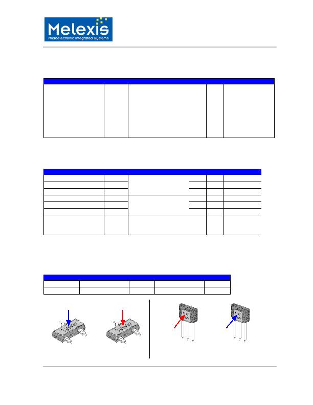
8 Output Behaviour versus Magnetic Pole
o
o
DC Operating Parameters T
A
= -40 C to 150 C, V
DD
= 3.5V to 24V (unless otherwise specified)
Parameter
Test Conditions (SE) OUT (SE) Test Conditions (UA) OUT (UA)
South pole
B < BRP
High
B > BOP
Low
North pole
B > BOP
Low
B < BRP
High
Table 5: Output behaviour versus magnetic pole
South pole
North pole
North pole
South pole
OUT = high
OUT = low (V
DSon
)
OUT = high
OUT = low (V
DSon
)
SE package
UA package
发布紧急采购,3分钟左右您将得到回复。
相关PDF资料
US2881LSE-AAA-000-RE
IC LATCH CMOS H-S TSOT-3L
XC3202B183MR-G
IC SENSOR HALL OMNI SOT23D
ZMY20MTA
SENSOR MAGNETIC W/MAGNET SOT223
ZMY20TC
IC FIELD SENSOR W/MAGN SOT223
ZMZ20M
SENSOR MAGNETIC 4PIN E-LINE-4
ZMZ20
SENSOR MAGNETIC 4PIN E-LINE-4
25LB22-H
ENCODER MECHANICAL 16POS HEX
11-71315-227-01
TOUCH SCREEN C1500SS SLIM BEZEL
相关代理商/技术参数
US1881LSO
功能描述:IC LATCH CMOS MP SOT-23 RoHS:否 类别:传感器,转换器 >> 磁性 - 霍尔效应,数字式开关,线性,罗盘 (IC) 系列:- 标准包装:1 系列:- 传感范围:20mT ~ 80mT 类型:旋转 电源电压:4.5 V ~ 5.5 V 电流 - 电源:15mA 电流 - 输出(最大):- 输出类型:数字式,PWM,8.5 位串行 特点:可编程 工作温度:-40°C ~ 150°C 封装/外壳:20-SSOP(0.209",5.30mm 宽) 供应商设备封装:20-SSOP 包装:Digi-Reel® 其它名称:AS5132-HSST-500DKR
US1881LUA
制造商:MELEXIS 制造商全称:Melexis Microelectronic Systems 功能描述:Hall Latch - High Sensitivity
US1881LUA-AAA-000-BU
功能描述:IC LATCH CMOS MP TO-92UA RoHS:是 类别:传感器,转换器 >> 磁性 - 霍尔效应,数字式开关,线性,罗盘 (IC) 系列:- 标准包装:1 系列:- 传感范围:20mT ~ 80mT 类型:旋转 电源电压:4.5 V ~ 5.5 V 电流 - 电源:15mA 电流 - 输出(最大):- 输出类型:数字式,PWM,8.5 位串行 特点:可编程 工作温度:-40°C ~ 150°C 封装/外壳:20-SSOP(0.209",5.30mm 宽) 供应商设备封装:20-SSOP 包装:Digi-Reel® 其它名称:AS5132-HSST-500DKR
US18-PA-5-N03-IH
制造商:IDEC CORPORATION 功能描述:95B040020 Sensor Ultrasonic
US18-PA-5-N03-OH
制造商:IDEC Corporation 功能描述:SENSOR, M18 STRGHT BARREL NPN/PNP OUTPUT 制造商:IDEC Corporation 功能描述:95B040000 Ultrasonic M18Sensor
US18-PA-5-N03-VH
制造商:IDEC Corporation 功能描述:95B040040 Ultrasonic M18Sensor
US18-PR-5-N03-IH
制造商:IDEC Corporation 功能描述:95B040030 Sensor Ultrasonic
US18-PR-5-N03-OH
制造商:IDEC Corporation 功能描述:95B040010 Sensor Ultrasonic